Day2!!
Example files
https://github.com/chimanaco/td-workshop-vivo201902
Day2 > Day2.toe
Agenda for today
- Any questions from last week?
- Audio
- Conversion operators
- Basic 3D rendering
- Geometry Instancing
- Audio Spectrum visualization
- More audio
- PBR (Physically based rendering)
- Open lab time
Hey it's day2!!
Today we will learn how to make an audio spectrum visualizer in TouchDesigner. Let's get an idea what it looks like before we start working on it.
Example1: /project1/Audio_spectum_result
I can break it down into four sections like the below, so let's take a look at some basic methods and techniques we are going to use before actually making it.
- Audio
- Conversion operators
- Basic 3D rendering
- Geometry instancing
Audio
Audio in TouchDesigner sometimes sounds weird when other processes are working heavily, especially when there's lots of video processing going on. You could create multiple toe files and work with audio and video separately, but it might be a better option for you to work with audio in an application like Ableton Live, Max/MSP or any music production application.
Anyway, there's still a lot we can do with audio in TouchDesigner :)
Example1: /project1/Audio_in_and_out
Firstly, let's just play an audio file. If you open the OP Create Dialog and go to the CHOP tab, there are a bunch of operators with the prefix Audio that are specially designed to work with audio. We will use the Audio File In CHOP to play an audio file in TouchDesigner. Go to the CHOP tab and find Audio File In CHOP and drag it to the Network Editor. It will automatically start playing the sample file that TouchDesigner provided. In this case it's an .mp3, but you can use various type of audio files such as .aiff or .wav. You can specify your own audio file like we did with Movie File In TOP on Day 1.
We also have an Audio Device In CHOP, you can get input from microphones or other audio devices into your computer. If you choose your microphone as a Device, you will see the waveform corresponding to what's happening with audio input.
Output audio
You won't hear anything until you output the audio via your speakers. To do that, we can use Audio Device Out CHOP. Double check the volume of your computer before connecting this CHOP because sometimes we don't know how high the volume is. Especially when you use headphones..
If you have an audio interface, when you add the Audio Device Out CHOP to the Network Editor, you might have to choose your driver and device on the parameter Window. There are also parameters for changing Volume and Pan.
Audio Spectrum
There is also a CHOP called Audio Spectrum CHOP. If you just plug in your audio into this, it will give you a visualization of your audio spectrum which can be used for creating lines, printing graphics and so on. It's doing an FFT on your audio and getting the intensity of all the different frequency ranges so it's nice for visualizing. We're going to use this later tonight.
Conversion Operators
We have learned that we can connect operators in the same family with a wire and also how to make a reference when we export data from one format to another.
I would like to introduce Conversion Operators that we might use often in our work. You can convert data between different Operator families using them. Let's take a look at two of them because we are going to use them later today.
If you're interested, take a look at Converting data between OP Families for more families.
Top to CHOP
Example: /project1/TOPto_CHOP
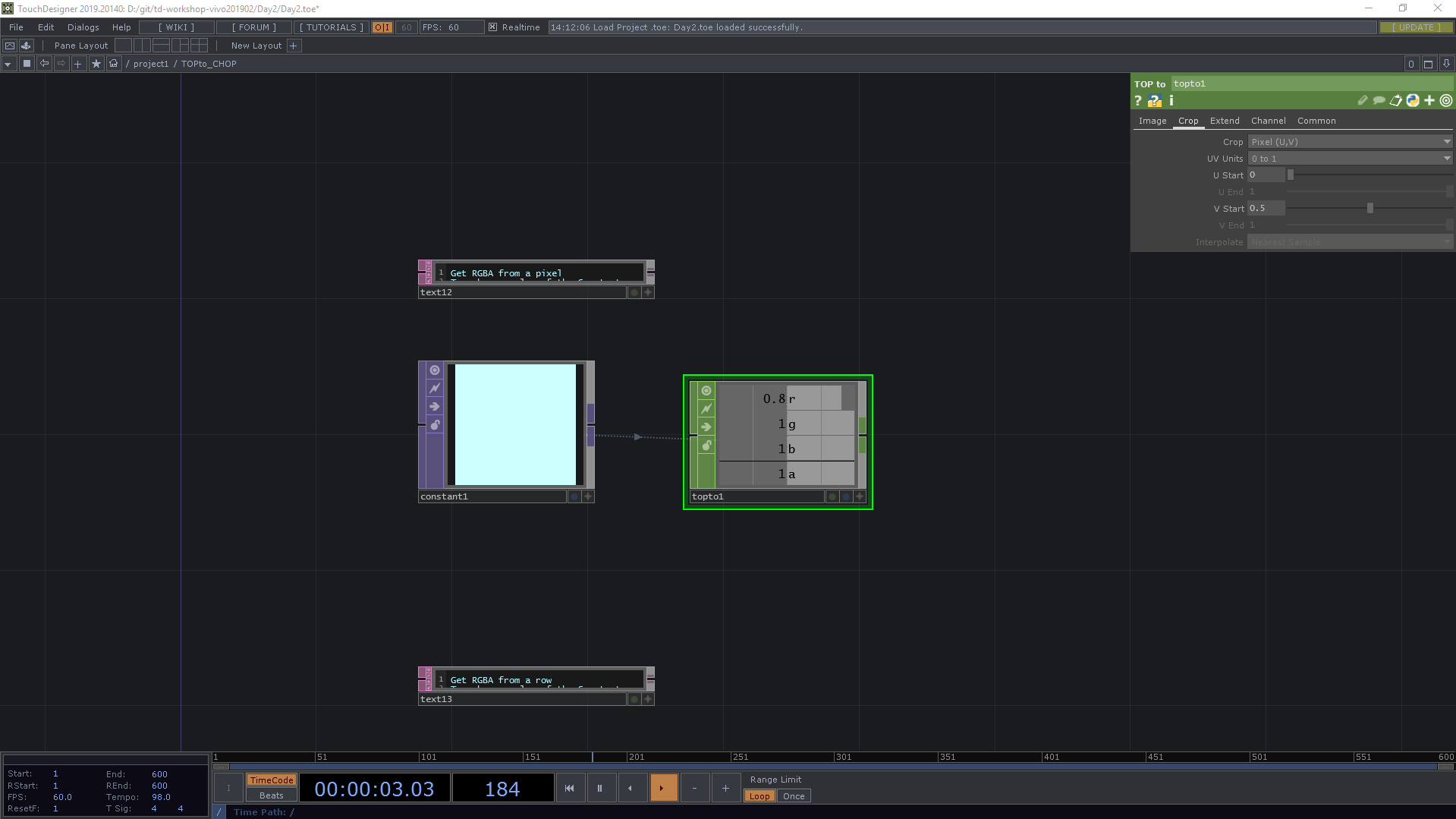
TOP to CHOP is the CHOP that converts pixels in a TOP image to CHOP channels.
You can get values from a single pixel. Choose Pixel(U, V) for the Crop parameter.
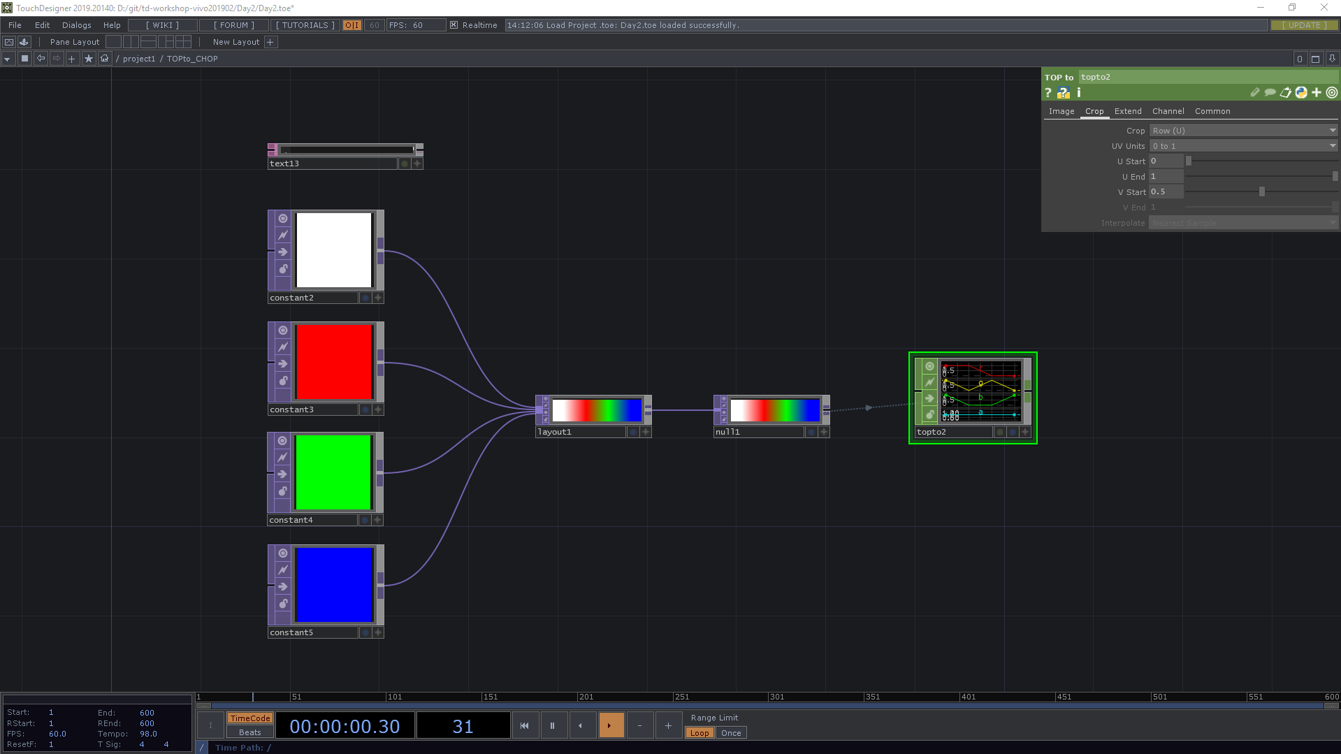
You can get values from rows of pixels. Choose Row(U) for the Crop parameter.
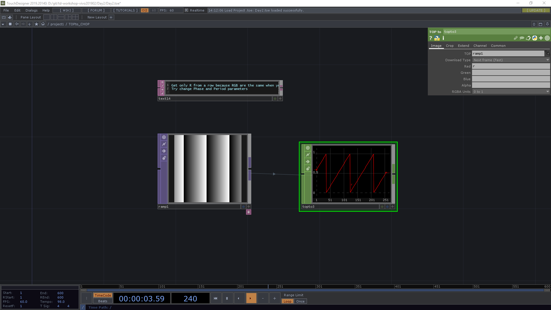
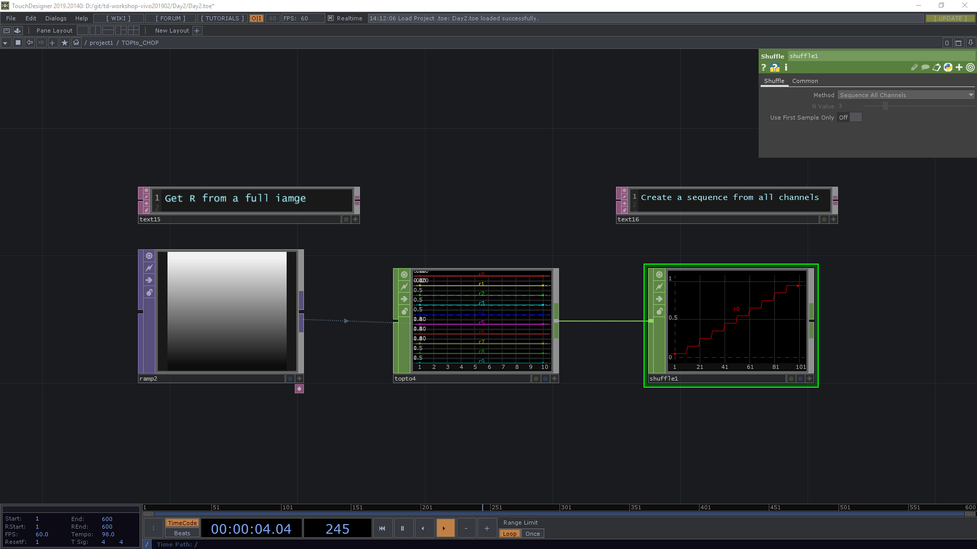
We often use only R value from a gray-scale image.
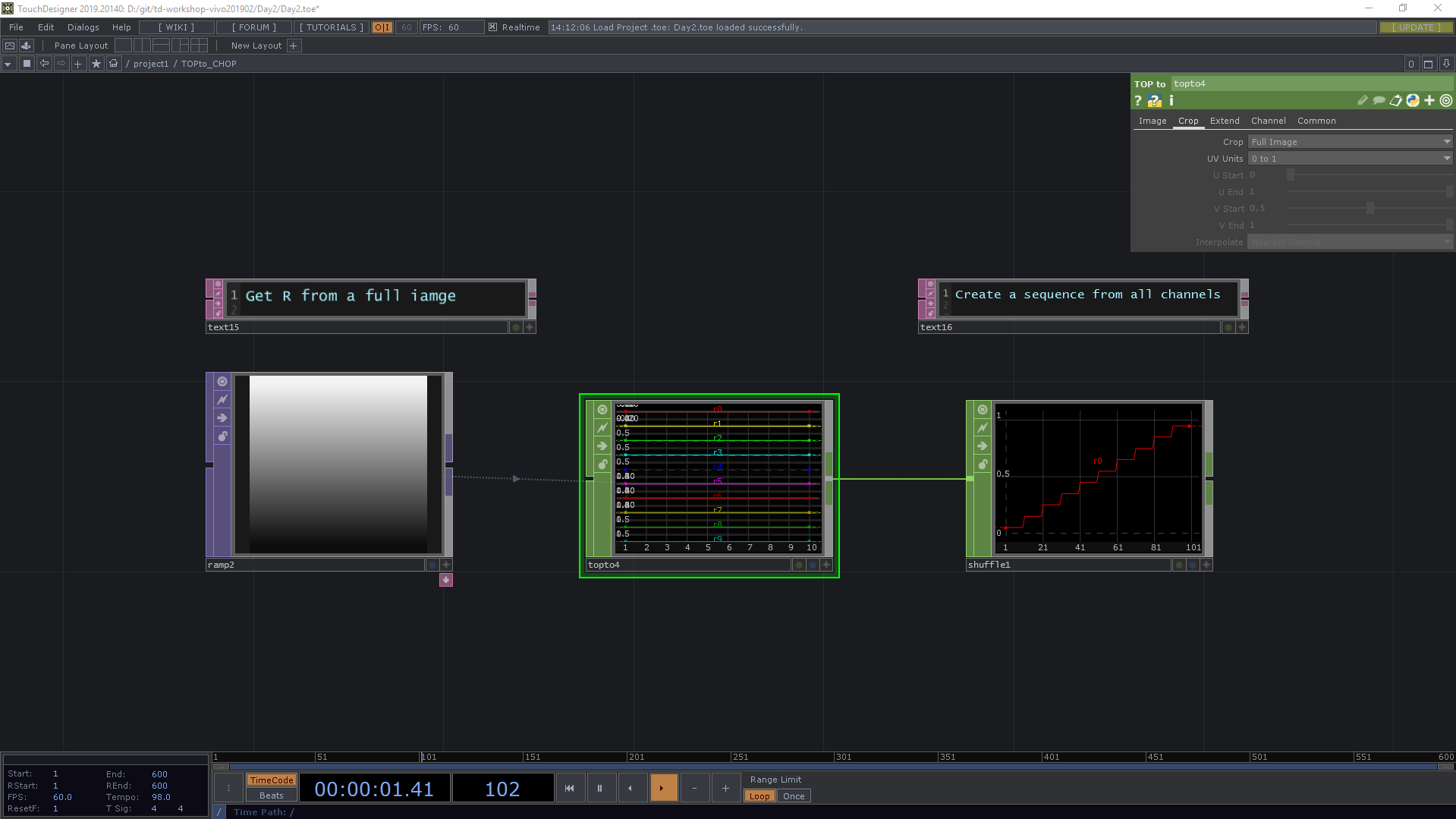
We also can get values from a full image.
If you make animation, you'll see a CHOP will animate too.
Basic of 3D Rendering
Let me speak about the very basics of 3D rendering in TouchDesigner.
Geometry Component
Example: /project1/Render_minimum
Firstly, let's have a look at a Geometry COMP. Go to the COMP on the OP Create Dialog tab and find Geometry. You will see a torus here.
I would like to show you a few things about working in the Geometry viewer. If you make that viewer active you can tumble by left mouse button and zoom by middle mouse button and moving left and right but more importantly there are options for looking at your geometry.
You can open a small dialog by right clicking and choose Display options. Here You can turn on your points so you can see where every point of the topology of this torus is. If you need to look at point numbers, you can do that too.
You can also check out its normals. Normals are perpendicular to the face of a polygon. A normal would be pointing at 90 degrees out from the face and this is used by the rendering engine for lighting calculations because you need to know which way your geometry is facing to know how to light your geometry.
It's important to know because sometimes, for one reason or another, normals aren't included in import geometry that you downloaded from the internet or from another application. That can be a pain.
The other thing about this is a wire-frame. You can switch to the wire-frame state with the W key. Often you need to use wire-frame to inspect your geometry to see what's going on.
Rendering
Right now we're just talking about 3D objects and they're just raw objects in object space so we want to render this.
A Geometry COMP allows us to render it. Let's put down a Render TOP. This is taking a 3D scene and rendering it into a 2D image. If you add it, it looks like something happens but you can't see anything rendering.
The thing you need for every rendering is a camera. There's a warning here if you middle mouse click on it, it is saying no Camera COMP found. Your rendering is undefined right now, so let's add a Camera COMP under COMP.
Now we have a camera and we can see the geometry but it's black because the space is very dark without lights. So we need a light as well. So let's add a Light COMP. Now we can see the geometry.
On every SOP and Geometry COMP, we have flags for rendering and display, so I'm going to turn on the purple flag for rendering because I'm going to render this in it in a minute or two with you. I'm also going to turn on the display flag. The display flag just lets it be viewed in this viewer, so if I go inside and turn off the display flag you won't see it in the viewer. This is for situations where it doesn't make sense to turn it off, for instance you might have proxy geometry or you might have like a bounding box that you actually don't want to view but it's in there doing something. So you can turn off the display of things or the rendering of things. For example, I might have a light in my scene, I don't want the light to be rendered but I want to see it in my view so this is how you control those things in a 3D scene.
If you want to work on this in a 3D environment, you can split your panes into two workspace and have a 3D viewer on the right.
You can select this horizontal split and now you have two panes to work in. This is going to be handy when you're working on this upper lever and then you want to go inside and work on your geometry you can do two things at once. In this case I was interested in showing you how to get a geometry viewer here and this drop down menu at the upper left of any pane allows you to select different types of viewers. I'm going to select a geometry viewer and now I can see my scene in 3D.
We can also add material. Let's try one of them called Phong on the MAT tab on the OP Create Dialog. On the Geometry COMP, if you go to the Render tab, you can drag your Mat to the Material parameter. Or you can type in phong1, that works as well.
The material lets you control all sorts of things. I can control just the diffuse color or I could change the specular color.
Geometry Instancing
Example: /project1/SOPto_CHOP_Instancing
Another way to create a geometry
Let's drop down another SOP called a Box SOP which is just a 3D Box. Last time we just chose a Geometry COMP from the Dialog, but I would like to show how to add the geometry in a different way.
Let's remove the geometry we have. Then left click on the output of the Box SOP, go to COMP and choose Geometry. Now you automatically have your SOP inside the geometry. If you go inside the geometry, you see In SOP and Out SOP here. If you go back to the upper level, you see that there's an input and an output for SOPs.
Every family has these in-and-out operators because you can do this for CHOPs or TOPs or DATs. You can send data into a component, work on it like a black box, and then spit it out the other side. You can make it like a plug-in or an effect. We won't use this output today, but we could add another SOP and keep on going down the chain.
I would like to add a Transform SOP here. So transform is something you do a lot in 3D space. Transform just means moving rotating and scaling. Add a Transform SOP between the BOX SOP and Geometry COMP and put 0.01 for Scale xyz. We will tweak this value later.
Primitive types of SOPs
Let's drop down another SOP called a Sphere SOP which is a 3D Sphere. I choose this because it is a good indication of the different Primitive types we have in TouchDesigner. We have Mesh, by default. NURBS are beautiful and smooth, but they're very intensive for the CPU to calculate, so for real-time we don't use them too much if you're animating them. If it's a non animating surface you can use NURBS. There are also Polygons. Now you can't see too much of a difference here but if I make it wire-frame, you can see that a Mesh is made up of Quads and a Polygon is made up of triangles so different ways of working here.
Sometimes one could be lighter than the other. If you inspect it you can see how many points and polygons you have. And one thing to consider when you're working in SOPs is all the SOPs are calculated on the CPU. So when you increase your point numbers and you start animating things it will slow down a bit.
If you want to know how long something is taking to calculate, every operator has CPU cook time. If you look at it, it says this is 0.83, for example, that's how long it took to calculate that node. If you're running at 60 frames a second you only have 16 milliseconds to get all your work done. You can think of that as your budget you have 16 milliseconds and everything you do is spending some of the budget because you don't want to drop frames you want to try to say it's 60 if you can.
SOPto CHOP
Add Null SOP after the Sphere. And then I would like to introduce another conversion operator. Left click on the output on the Null SOP and choose SOP to. SOPto_CHOP is the CHOP that uses a geometry object to choose a SOP from which the channels will be created. The channels are created from the point attributes of a SOP, such as the X, Y and Z of the point position.
If you take a look at the SOPto CHOP, you see three channels which are tx, ty and tz. Those are information for all xyz positions. Add Null CHOP after the SOPto CHOP.
Geometry Instancing
There is a feature called Geometry instances in TouchDesigner. Geometry instances in the Geometry Component are copies of the geometry object, which can be transformed independently. The Geometry COMP has an Instance parameter page to create instances. You can have one instance for every sample of a CHOP, row of a table, pixel of an image, or point of a SOP. Transformations of the instances can be made by supplying CHOP channels with X, Y, and Z and other data, for example.
Here we would like to create instances of the Geometry which has Box SOP inside using the CHOP data that we got from the Sphere SOP. To do that, select the Geometry COMP, go to Instance tab and turn it on for Instancing at the very top. And then drag and drop the Null CHOP which is connected to the SOPto CHOP onto Instance CHOP/DAT/SOP. Now some parameters for instancing are available for us!
As we saw, if you go to the Null CHOP, there are 3 channels named tx, ty and tz. We can use these samples for the position of the instances. Choose tx at the arrow on the very right hand side of Translate X, ty for Translate Y and tz for Translate Z. Now we have boxes located on the sphere's points.
Create Audio spectrum visualizer
Finally it's time for the visualizer!
CHOP
We have Audio File In CHOP and Audio Spectrum CHOP here. I would like to add Envelope CHOP, which takes a maximum and is used to normalize the value from -1 to 1. Then add a Math CHOP, connect the Audio File In CHOP first, and then connect the Envelope CHOP. Select the Math CHOP and select Divide for the Combine CHOPs parameter. Now we have samples from -1 to 1.
Insert another Math CHOP after the last Math CHOP and select Average for the Combine Channels parameter. Now we have one audio spectrum.
TOP
I would like to re-sample this and convert it into 200 samples. As we saw the final result, we will have 200 x 200 blocks for the visualizer.
Add a Resample CHOP after the Audio Spectrum CHOP. Go to Common tab and toggle Time Slice off. Then go to Resampletab, select New Rate, New Interval for Method and Absolute for Unit Values. Also select Samples for dropdown for Start and End.
Add a Resample CHOP after the Audio Spectrum CHOP. Go to Common tab and toggle Time Slice off. Then go to the Resample tab, select New Rate, New Interval for Method and Absolute for Unit Values. Also select Samples for dropdown for Start and End.
Here I want to put a variable for its size because we will use this value for several operators later. Let's add a Constant CHOP, rename it Variables and rename chan1 to size and put 200 for its value. Let's make a reference from the size channel to End parameter and add -1. The expression for End will be op('Variables')['size']-1.
Here I would like to convert this CHOP to TOP. Add Null CHOP and Right click on the output of the Null CHOP and select CHOP to TOP. Then we have 200 x 1 image. If a sample is closer to 0, it visualizes as black-ish and if closer to 1, it looks white. It's a grayscale gradation.
I want to make a 200x200 TOP because I will use it to determine some parameters for the final 3D output. Go to the Common tab. Select Variables where we put 200 as its size, click the right bottom button, drag the size channel to the resolution and select CHOP Reference and choose Resolution for Output Aspect. Now you see 200x200 Rectangle. Or you can just type in op('Variables')['size'] there.
Then if you put 1/op('Variables')['size'] for scale y which is the right on Scale, you have the 1 pixel line you had at the chopto1 at the center. And then put 0.5 for Translate Y. because I want to bring it to the top of this texture.
Add Level TOP after the Transform TOP and put in a Gamma value, let's say 2.2 to brighten the white pixels. Also add Null TOP after the Level TOP.
Let's make our feedback loop. Add a Feedback TOP and an Add TOP onto the Network. Get wires by right-clicking on output of the Null TOP we just added and connect it to input1 for the Add TOP and connect the Feedback TOP to input2 of the Add TOP and specify add1 as Target TOP of feedback1. Now we have a feedback loop.
Let's put more TOPs onto this feedback loop. Right-click on the wire connecting feedback1 and first input of add1. Firstly, you can put Transform TOP. Put -0.015 for Translate Y. I use a minus number here because we want to move texture from top to bottom.
Secondly, add a Level TOP to create a fade. Put 0.965 for Opacity and then we have a fade effect.
Lastly, let's add a Blur TOP which basically blurs an image. I want to adjust two parameters here, one is Pre-Shrink which reduces the image's resolution before applying the blur. Another is Filter Size, which is the amount of blur in pixels. Consider using Pre-shrink when the blurs are high and you want to optimize performance. Here I choose 2 for Pre-Shrink and 7 for Filter Size, but try different parameters as well.
SOP
I'm going to leave the texture we have made at this moment. We will use this texture later.
Move to where we put Sop to CHOP after Sphere SOP. For visualizer, we would like to layout our boxes on the grid. We have a Grid SOP to do this job. It is commonly used because the grid can be used for anything, for example, a virtual screen in your 3D space o put a movie on, or a ground plane and so on. Let's put a Grid SOP on the Network Editor.
If you right click on the SOP, you can find it saying 400 points on the information. This grid has 20 rows and 20 columns right now, but we want to have 200x200 grids here.
Let's change the rows and columns. Instead of dragging and dropping size channel of Variables, you can just type op('Variables')['size'] for Rows parameter and choose expression. Then you will have 200 there.
I would like to have the same value for Columns, but let me introduce another way to do it. Right click on the name of Rows and choose Copy Parameter. Then Right click on the name of Columns and choose Paste Reference. Now you should have 200 for the parameter and the expression should be me.par.rows.
Here me is a operator itself, in this case the grid1 operator. par means parameter and rows means a name of the parameter. You can find its name for expression by clicking plus button on the very left of a parameter. For example, you can also use sizex and sizey for the name and the expression would be me.par.sizex. Then you should have the same value as one for sizex.
I would like to change my 3D scene a bit. Select the Camera, type geo1 for Look At. 0, 1, 0.3 for Translate and 0, 0, 1 for Orient Up Vector. Then select the Light and put 0, 0, 4 for Translate and wire from its top to the bottom of the Camera. This gives us a parent-child relationship between the camera and the light.
Then add a Null COMP to the editor and put absTime.frame/10 for Rotate z. Wire from the top of the camera to the Null COMP. Then the camera should start rotating.
We can also specify colors on instances. Currently we have samples ranging from -0.5 to 0.5. Let's map this in order to use these as values for colors. R, G and B colors in TouchDesigner go from 0 to 1.
Middle click on the output on the SOP to CHOP and add a Rename CHOP and put r g b for To. Then add a Math CHOP to map those channels. Go to the Range tab and put -0.5 and 0.5 for From Range.
We have used null1 as a reference, so we would like to add more channels here. To combine samples from multiple CHOPs, we can use Merge CHOP. Add a Merge CHOP to the Editor and connect outputs from sopto1 and math1 to the input of the merge1. And then connect merge1 with null1. Now we have a CHOP which has 6 channels, tx, ty, tz, r, g and b.
Select the Geometry COMP and go to Instance2 tab. Select r, g, b for R, G, B parameters. You will see gradient color on those boxes.
Let's go back to the texture we worked with earlier. Select the Null TOP right after our feedback loop and right click on the output of it and choose TOP to from the CHOP tab.
In the TOP, just delete values from Red, Green and Alpha because we are going to use only r here. Go to the Crop tab, select Full Image for Crop. I would like to have one sequence from this r channels. Let's add a Shuffle CHOP, which reorganizes the samples in a set of channels. Select the Shuffle CHOP and select Sequence All Channels for the Method parameter. Then add another Rename CHOP and put scalez for the To parameter.
Let me exaggerate this value a bit, so add Math CHOP again and enter 40 for the Multiply parameter. You can put any number here.
Finally, connect this to the Merge CHOP where all channels are together. Then select the Geometry COMP, go to Instance tab and select scalez for the Scale Z parameter.
Select the Transform SOP after the Box SOP, put me.par.sz/2 and turn expression on so that we can scale the boxes to z axis from the plane.
We can use the r samples we got from the texture for colors as well. All of b is 0 at this moment, so I would like to use the r samples for b. We can do this in the same way as scalez, but say, we use 3 for Multiply and b for its name.
Using Select CHOP, select only r and g from the Sop To CHOP. And then you can connect Rename CHOP which now has a b channel with Merge CHOP. Now colors are also changing based on the height of the bars.
Audio analyzer
Example: /project1/Audio_analyzer
Audio Analysis COMP
Example: /project1/AudioAnalysisCOMP
PBR Rendering
Example: /project1/PBR_bg
Make Beats
It's just a dirty clone of Make beats | Learning Music (Beta) in TouchDesigner.
Day2 > Make_Beats.toe
Open Lab time!
For lab time today, I would like everyone to play around audio visualization based on what we have learned!
References
- Audio spectrum wave pinboard, TouchDesigner tutorial - YouTube
- Introduction to TouchDesigner - Ben Voigt - YouTube
- TouchDesigner Audio Spectrum Trail Heatmap Tutorial - YouTube
- Aurora Audio Spectrum – TouchDesigner Tutorial 2 - YouTube
- Spectrum to TOPs – TouchDesigner Tutorial 8 - YouTube
Question about the workshop?
Feel free to contact me. I am also available to run other TouchDesigner workshops either online or offline.
- chimanaco (at) gmail.com
- Instagram @chimanaco
For the attendees of this workshop, post your question in the Slack channel I invited you to so that anyone in the workshop can obtain benefits from your question.